Room acoustics and microphone recording for the Voice
- Author Profile
- Recent posts

Pianist, Composer, Arranger, Sound Engineer, Writer, Blogger
Alessandro Fois is a musician, composer, pianist, arranger and sound engineer. Since 2018, he has also been a writer, blogger and webmaster. He currently resides in Ivrea (Turin) where, in addition to the above activities, he manages Lycnos, studio for audio, video and web services, and the recording studio Glamour Recording Studio.
Room acoustics and microphone recording for the Voice
A large room, given the same treatment, will still sound better than a small room.
In large rooms, in fact, some of the most serious acoustic inconveniences, such as those caused by the standing waves and phase shifts from first reflections result in fewer accidents and are much easier to solve.
Let us see these drawbacks in brief.
First reflections
First reflection is the sound wave that, before reaching the microphone (or the listener's ear), is reflected on a single wall (a side wall or the ceiling of the room, or any other reflective surface such as a table, furniture or other).
The microphone (or ear) will then receive two copies of the same source:
- one direct from the source
- the other reflected from the reflecting surface, with lower volume and having a more or less altered sound colour depending on the characteristics of the reflecting body and, above all, slightly delayed (time lag) compared to the direct one
The above-mentioned time lag will produce an alteration, in the form of comb filter, of the resulting wave perceived by the microphone (created by the superposition of the two superimposed waves), creating the cancellation of certain frequencies and generally modifying and impoverishing the sound considerably.
The negative effect of this will be more pronounced in cases where the reflected wave maintains a higher volume than the direct wave.
This happens:
- when the source is very close to the reflective surface
- when the surface itself has a high reflective power
It follows that the solutions may be as follows:
- cover reflective surfaces with sound-absorbing material capable of attenuating even the lowest frequencies of the source
- move the source as far as possible away from reflective surfaces (it follows that in a room a position close to the centre is best in this respect)
- reduce the distance between the singer's mouth and the microphone
- interposing between source and reflective surface a sloping moving panel capable of deflecting reflections away from the microphone
As is obvious, the above-mentioned solutions can also be used together (e.g. 1 and 2 at the same time).
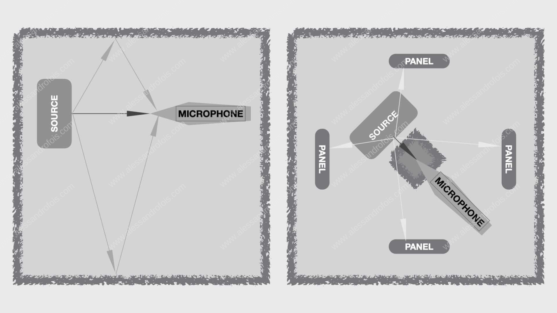
On the left a shot affected by overlapping waves generated by the first reflections. On the right a total resolution of the problem by changing the position of the microphone and interposing sound-absorbing acoustic panels at strategic points.
Standing waves and bass traps
The resonances and frequency gaps (caused by standing waves in fact, which are a function of the size of the room itself) in fact become lower and lower in frequency as we enlarge the room's n.3 dimensions.
Sufficiently large rooms then (e.g. m.7Wx5Lx4H or larger), will not cause any serious inconvenience to male (lower range) voices and certainly not cause any appreciable inconvenience to female voices.
If you have a smaller room, it will be essential to carpet the corners and front, side and ceiling walls corresponding to the chosen microphone pick-up point with so-called 'bass traps'.
NOTE
For the voice, since it is not an instrument capable of descending to very low frequencies, bass traps capable of attenuating medium-low frequencies such as those in the frequency range between 80 and 400 Hz are recommended.
Therefore, do not consider bass traps tuned to lower frequencies (20 to 80 Hz) unless you have to shoot low-pitched instruments (bass drum and timpani, bass and double bass, etc.).
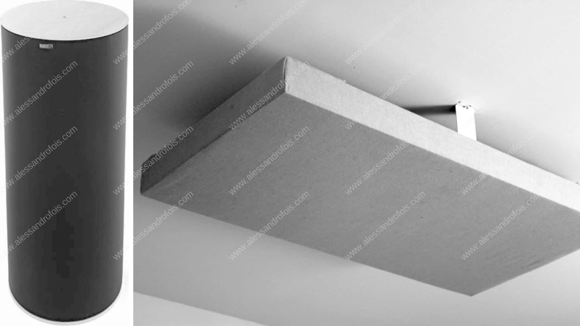
Some examples of bass traps: on the left a cylindrical one for low frequencies, on the right a ceiling-mounted retangular one for medium-low frequencies (very suitable for vocals).
In any case, if you can, do not use rooms with two or even three equal or nearly equal dimensions, nor rooms in which one dimension is multiple or approximately multiple of another.
In such rooms, the resonance effect and holes at specific frequencies would be further exacerbated.
Flutter echo
Echo flutter occurs when walls face each other at short distances, when they are sufficiently parallel to create a ping-pong of echoes in rapid succession and high intensity.
As is obvious, this inconvenience can occur in both small and larger rooms.
To prevent the onset of Flutter echo, we can:
- eliminate the parallelism of opposing walls by means of diagonal counterwalls, or by interposing sloping panels on the sides of the source or against the walls
- papering the walls, at least at crucial points, with sound-absorbing panels with pyramidal spires capable of absorbing frequencies up to 120 hz (lower down will be very difficult with such panels); for good results, panels with 10 cm thick pyramidal spires are recommended
- instead of sound-absorbing panels, it is possible to use diffuser panels with the capacity to spread the same frequencies (this is a better but more expensive choice)

On the left, the source (S) maximises the flutter echo phenomenon; to its right, two absorbing panels considerably dampen the effect; to the right, the effect is dispersed by the non-parallel walls.
Reverberation times
In any type of room, it will also be desirable to create a sufficiently diffuse but still sound, with a reverberation time of 0.5 seconds or less.
This can be achieved with the appropriate use of sound-absorbing panels, speaker panels and bass traps on the walls.
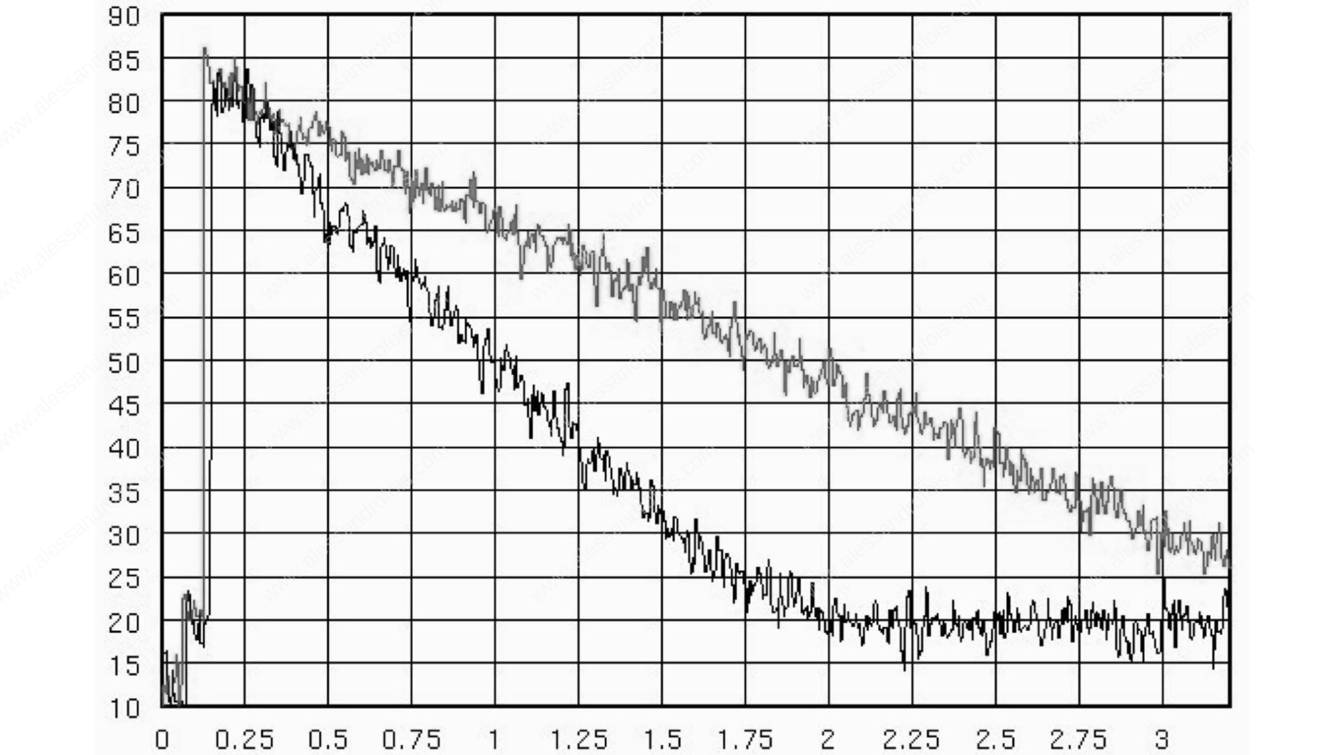
In the diagram above we see the long decay time of the reverberation caused by a blow of the hands (60 db attenuation after almost 3 seconds). In the example below, we see a considerable shortening of the reverberation decay time (60 db attenuation after less than 2 seconds) by means of a large, thick carpet on the floor. By adding absorbing surfaces, the duration of the reverberation will decrease.
For a better handling of the above, I would again direct you to the above-mentioned book, which deals more precisely and comprehensively with the subject of the treatment of a home studio's recording room:
"Home studio for digital recording"
www.alessandrofois.com/home-studio-per-digital-audio-recording/
Microphone position
Last but not least is the choice of where in the room to place the pick-up microphone.
The purpose of this choice is to optimise the pick-up point, so that the main stationary modes do not affect or affect the sound to a lesser extent, creating inappropriate reinforcement or (worse) frequency holes.
Without explaining to you how to do the calculations (which you will find in the book mentioned above), know that:
The main modal nodes where the cancellation of frequencies takes place (those corresponding to standing waves, which are a function of the room size) are located at the following distances between the opposing walls of all three room sizes (W, L and H):
- 0 % and 100 % - incidence of 1st level cancellation (maximum incidence)
- 50 % - 2nd level cancellation incidence
- 33.33 % and 66.66 % - incidence of Level 3 cancellation
- 25 % and 75 % - incidence of 4th level cancellation
- 20 %, 40 %, 60 % and 80 % - 5th level cancellation incidence
- 16.66 % and 83.33 % - incidence of 6th level cancellation
- 14.28 %, 28.57 %, 42.84 %, 57.12 %, 71.43 %, 85.72 % - incidence of 7th level cancellation
- 12.5 %, 37.5 %, 62.5 %, 87.5 % - incidence of 8th level cancellation (lowest incidence)
It will therefore be inadvisable, in principle, to position the microphone at the above distances for each of the three room dimensions.
Above we have considered 8 levels of modal nodes, whose incidence decreases from a level 1 (maximum) to a level 8 (minimum among those contemplated - in reality there are infinite levels of ever decreasing incidence); of these at least the first 4 should be considered carefully.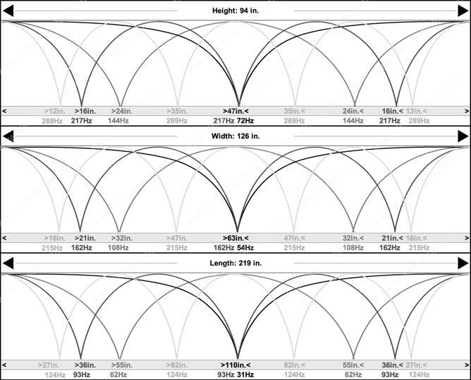
As an example, here is a schematic representation of the 3 dimensions of a room (expressed in inches). Highlighted are the points of maximum reinforcement and frequency gaps that can occur at precise geometric distances depending on the distance between the walls.
We can say that:
- levels 1, 2, 3, and 4 should be strictly considered
- levels 5 and 6 should be taken into account especially in small rooms
- levels 7 and 8 could also be neglected
Simplifying:
Let us consider percentage measurements: 0 20 25 33 40 50 and the complementary 100 80 75 66 60 50
In bold font the values always to be considered
In normal typeface those to be considered incidental, but more important in small rooms
The other measures can all in all be neglected for the sake of simplicity
NOTE
It should be noted that these percentages refer to a usual room in the shape of a regular parallelepiped; in other cases the calculation of these proportions would be very complex, but the above table may serve as a reference guide
Bear in mind that distances closer to the walls are inadvisable in order to reduce the incidence of first reflections, which have minimal incidence towards the centre of the room.
Consequently, the ideal distance of the spot where to place the microphone is:
- IDEAL: the 46% and its complementary 54% of the distance between two opposing walls, including the distance between floor and ceiling.
- GOOD: if the above is not feasible, consider the 77/78% (and its complementary 22/23%) or the 69% (and its complementary 31%)
- ACCEPTABLE: in the absence of other possibilities, use the 64% (and its complementary 36%)
Let's take an example.
If you have a room with the following dimensions: m.4Wx3Lx2.70H, these are the recommended distances for the microphone:
- W m. 4.00 = ideal distance is m. 1.84 (46%) or m. 2.16 (54%)
- L m. 3.00 = the ideal distance is at m. 1.38 (46%) or m. 1.62 (54%)
As far as height is concerned:
- with a room having H m. 2.70 = a singer with a height of 1.60 m would be at 59% of the height - looking at the table we see that it is not ideal but tolerable
- with a room having a H m. 2.70 = a singer with a height of 1.70 m would be at height 63% - looking at the table we see that it is not ideal but tolerable
- with a room having H m. 2.70 = a singer with a stature of 1.80 m would be at height 67% - looking at the table we see that this is too close to a 3rd level node, so it would be advisable to modify the height of the singer (and therefore of the microphone) with a small platform
To conclude: for practical reasons, for the height we can make do with an approximate measurement, avoiding (if possible) matching the height of the microphone with one of the incidence percentages from 1 to 4.

On the left, the microphone (M) has been placed at a point near the centre of the room, corresponding to the 46% of the room's width and length measurements, which is generically the ideal point for acoustic pick-up. As far as height is concerned (right), the position of the microphone will essentially depend on the height of the singer; the n.5 examples represent the positioning of the microphone as a percentage of the height of the room, which in the example is m.2.7054% would be the ideal height but would correspond to a person only 146 cm tall; then 59% is the height for a person 160 cm tall and 67% for a person 170 cm tall, both not ideal but acceptable measurements; 67% is the measurement for a person 180 cm tall, this measurement is not ideal and would become more tolerable with a few centimetres of raising by means of a platform, to arrive at 69%. Generally speaking, however, height can be considered a negligible element for practical reasons, merely correcting for microphone heights that are in the middle, thirds and quarters of the room height measurement.
Mobile panels and screens
Beyond the requirements of preventing the inconveniences caused by standing waves, reducing flutter echo and limiting reverberation times, it will often be useful to have some mobile sound-absorbing panels that can be positioned as required.
It would be even better if, on the opposite side, these sound-absorbing panels were covered with a diffuser panel, so that the most suitable of the two options can be chosen on a case-by-case basis.
With such panels it will be possible to adjust and attenuate the room acoustic influence at will.

Some mobile sound-absorbing panels.
For very small studios, there are some sound-absorbing screens on the market, with a semi-circular profile, which can be installed on a pole in order to position it behind and to the sides of the microphone.
This is not an ideal solution but can be adopted in small studios, especially where wall coverings are not sufficient for good overall acoustic correction of the room.
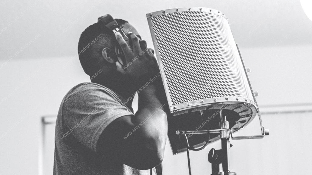
Sound-absorbing acoustic screen for singers, a simple mid-level solution in case of imperfect sound absorption in the room.
For more on Audio Recording, Editing and Digital Tuning


Leave a Reply
Want to join the discussion?Feel free to contribute!