Analogue and digital audio recording: considerations and comparisons

- Author Profile
- Recent posts

Pianist, Composer, Arranger, Sound Engineer, Writer, Blogger
Alessandro Fois is a musician, composer, pianist, arranger and sound engineer. Since 2018, he has also been a writer, blogger and webmaster. He currently resides in Ivrea (Turin) where, in addition to the above activities, he manages Lycnos, studio for audio, video and web services, and the recording studio Glamour Recording Studio.
Analogue and digital audio
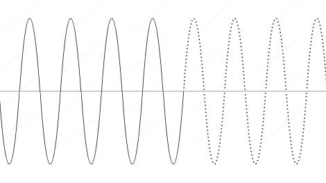
In the figure: on the left is the schematic representation of the wave related to the analogue signal and on the right (the dotted part) that related to the digital signal. It is intended to suggest the idea that the definition of the sound wave, in the digital, appears as a series of information pertaining to a level of intensity, discontinuous and more or less close together, represented by dots. By increasing the number of dots (thus increasing the resolution of the digital system), the information will merge into a continuous line, indistinguishable from the analogue one. In the same way, we want to suggest the idea (not entirely accurate) that in the analogue system the definition is instead representable as a continuous line, the result of the connection of infinite dots.
Unreconciled is the ongoing debate between the supporters of theanalogue and those of the digital.
If it can be a reference, I don't mind quoting the opinion of a musician who is considered one of the greatest conductors of all time: Herbert von Karajan, who as early as the 1980s firmly affirmed the absolute superiority of digital in reproducing the infinite tonal and dynamic nuances of the great symphony orchestra.
Put in terms of absolute quality, however, the question makes little sense, as digital and analogue audio processes are simply different and both have their pros and cons.
Through a simple direct comparison between the two worlds, we will be able to state something more, as we shall see.
Before going any further, we would like to emphasise that, beyond the quality comparison, the digital controls of the DAW will provide us with some unquestionable practical advantages not obtainable in the analogue environment:
- significantly lower purchase costs
- no wear and tear and no maintenance time and cost
- saving studio space
- reduced connection times and no wiring required
- reduced risk of malfunctions, which can be resolved with a simple restart
- possibility of replicating infinite 'instances' of the same plugin in the same work session (as in: I buy 1 and use 100 at the same time)
- storage of infinite setting memories
High Definition Digital
Comparison of definition and dynamics during recording
Let's start with a comparison between analogue and digital based on two very important parameters, namely definition and dynamics, which can be found during multitrack recording and during master production.
First, however, allow me to make a few clarifications:
It is necessary to dispel the 'absolute' idea that analogue has no 'resolution' or 'definition' of a limited kind, however high it may be. The alleged 'continuity of magnetic information' of the analogue tape is an abstract idea that only takes on conceptual significance in contrast to the digital method, as it has no real-world correspondence. In fact, iron oxide, which enables the magnetic storage of sound information, is composed of microscopic granules whose size is in fact a 'measure of resolution', in a different but analogous way to digital.
The empirical demonstration of the influence of the above can be seen by comparing the results that can be obtained by using different running speeds of the magnetic tape: higher speeds improve the linearity of the response especially at high frequencies, as well as perceptibly improving the overall fidelity; this happens because with each doubling of the speed, the number of magnetic information read by the cartridge is doubled; which is something analogous to what happens in the digital domain with the doubling of the sampling frequency.
The 'definition' of analogue, however, behaves differently from digital, as the storage of magnetic information is not as schematic as in digital: a lowering of the tape's running speed corresponds to a decrease in non-linear fidelity, resulting in a deformation of the sound, which will still remain 'listenable' and not 'grainy', as well as 'absent' at high frequencies, as would happen in digital by lowering the sampling frequency to only 24 Khz or even 12 Khz.
With digital with sampling frequencies from 44.1 Khz upwards, however, fidelity comparisons between the two systems take on greater practical meaning.
MASTER'S DEGREE PRODUCTION
ANALOG
A master engraved on analogue stereo tape with 1/2 inch width at high speed (30 IPS), thus using 1/4 inch for each mono track), produces excellent results in terms of definition and good results in the area of dynamics.
N.B.
30 IPS = 30 inches per seconds = approx. 76.2 cm per second
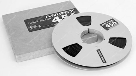
Ampex 456 Grand Master tape, one of the most popular analogue mastering tapes
DIGITAL
To reach a different level of definition, but in fact comparable to the above, it will be necessary to sample digitally at 24 bits at a frequency of 96 Khz.
Thus, for digital, very similar results will be obtained in the area of definition, but clearly superior in terms of dynamics due to the greater dynamic space determined by the bit depth.
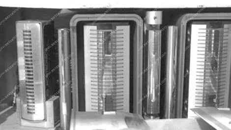
Detail of the head assembly of a 24-track analogue recorder
MULTITRACK RECORDING
ANALOG
Very good results, but somewhat less in terms of dynamics and definition, can also be obtained by working very carefully and expertly during multi-track analogue recording on 2-inch magnetic tape (24 tracks on 2 inches = 1/12 of an inch for a mono track) at a speed of 15 IPS (a speed not always used, to which the 7.5 IPS speed was more often preferred, in order to economise on the 50%'s size on the very considerable cost of magnetic tape of this type). .
Reducing the speed reduced the definition and especially the dynamic space in terms of signal-to-noise ratio.
In such systems, the crosstalk caused by the concurrence of tracks on the tape increases compared to the less significant crosstalk present on the master tape; however, there is maintains at a good level .
In order to keep the noise level relatively low and increase the effective dynamic space, noise reduction processes are often used and, when possible, there is a tendency to push the recording level up to the highest values of the tolerance sustainable by the digital tape, giving the sound a colour induced by progressive saturation, capable of modifying and in a certain sense enriching its harmonic content, which is often considered a merit, but not always.
One method of decreasing crosstalk is to use the sidebands of the tape for the more delicate sources, and also to avoid placing them next to others with high energy and similar frequency range (e.g. it was sometimes used to use tracks 01, 02 and 03 of the 24-track recorder for the HH and cymbals, leaving track 04 empty and continuing from the next track with the more energetic sources such as the snare drum, bass, and so on.
DIGITAL
In the realm of pure definition, recording digitally at 24-bit - 48 Khz, it could be argued that results will be slightly inferior to analogue recorded at 15 IPS, or slightly superior to it if recorded 7.5 IPS).
Digital will surpass analogue in the perception of definition using 96 Khz multitrack sessions.
In terms of dynamics, 24-bit or more digital will be significantly superior, allowing for a more 'relaxed' handling of levels during audio manipulation, thanks to the almost noise-free dynamic range.
Digital crosstalk is non-existent or almost non-existent, as it can only be produced during A/D conversion, and only in the case of simultaneous recording of several tracks.
Digital, by its very nature, is linear at every recording level and therefore does not offer the possibility of creating a progressive saturation depending on the recording levels (which can also have a creative value).
In return, it offers better fidelity in terms of a better correspondence with the original sound as recorded.
Sampling
Sampling at 48 Khz solved some of the problems initially imposed by 44.1 Khz; later, with 96 Khz, sampling was further optimised during production processes.
In the opinion of many sound engineers, however, the advantage offered by 192 or 384 Khz sampling is more virtual than real: such systems would offer little or no appreciable advantage, while taking away great power resources from the system, in both recording and processing.
On the other hand, the use of 88.2 Khz and 96 Khz files has its own valid reason, especially in the audio manipulation phases, while it can be overkill for end-user files.

Above is a free schematic-conceptual representation of the analogue definition of a sine wave, represented by a black line (in reality the absolute continuity of the line is more virtual than real) in comparison with its digital copies sampled at different sampling frequencies. It is evident that doubling the frequency allows a greater number of coordinates to be defined relative to the various levels of intensity and polarity of the wave in space-time. This results in a more faithful reconstruction of the original sine wave.
Bits and dynamics
We better evaluate the useful dynamic space.
Digital systems at 16 bits offer a range of 96 dbequal to or slightly below that of professional analogue, which at its peak, thanks to the considerable tolerance of the magnetic medium, could give us a few db more.
This advantage of analogue is, however, theoretical, due to the higher noise level associated with analogue recording, which subtracts several tens of db from the dynamic range at the lower end.
Signal to noise ratio
To put it briefly, the best professional analogue machines are capable of reproducing a signal-to-noise ratio (signal to noise ratio) fluctuating between 55 db and 73 db, depending on the quality of the tape and the recorder, the width of the magnetic strip of the tape, and the running speed used.
By means of circuitry Dolbyused mainly during the multitrack recording but sometimes also during the mastering to stereo trackthe signal to noise ratio could be increased by about 10-12 db, resulting in a useful dynamic range of as much as 85 db, which is remarkable but still less than that of 16-bit digital systems.
Advent of 24-bit
With the advent of 24-bit technology, the digital audio production process took a major step forward.
Each single bit can in fact encode 6 db of dynamic range, which means that with 24 bits we will have 48 db more dynamic range compared to the 96 db of the 16-bit 'system', for a total of 144 useful db.
This made it possible to virtually nullify every bit of background noise induced by the sampling process itself (except for imperfections in the A/D converters, depending on quality), allowing us to operate with levels even considerably lower than usual, also in order to prevent any risk of accidental clipping and to avoid unwanted saturation effects.
Further benefits came when 64-bit daw and floating point coding were introduced.
Such systems would be equipped with a theoretically high dynamic range, but they would still have to contend with 24-bit A/D and D/A conversion systems.
This does not therefore produce an appreciable increase in quality or dynamics in the produced file, but rather optimises the handling of dynamics during audio processing in order to
- Avoid clipping during rendering
- Greatly reduce numerical rounding errors required during signal processing
- allow the daw and 32- or 64-bit plugins to function 'natively', avoiding clipping (N.B.: in experimental practice, this is always true in 'precise' 32- or 64-bit plugins, as the case may be, while it is not always true in many 'coloured' plugins, such as some equalisers and emulation compressors)
The quality audio chain
In order to maintain a high level of quality, every link in the digital chain must be free from failure:
- virtual instruments
- A/D and D/A converters
- DAW
- plugins
- other possible related elements
In addition, another important element besides the individual quality of the components is the optimisation of compatibility between them in the area of sampling frequency and number of bits.
Each of the above should offer very high quality, and the working session should be set to a minimum value of 44.1 Khz or 48.0
If resources permit, even better at 88.2 or 96 Khz
The above, sampling at 24 bits or more, while retaining the convenient advantages of dynamic resource management.
Aliasing
To avoid or mitigate the aliasing problem, every good A/D converter should be equipped with an anti-aliasing filter at the input. Failing this, the use of a low-pass filter with a very pronounced slope, placed between the input source and the converter, could solve the problem.
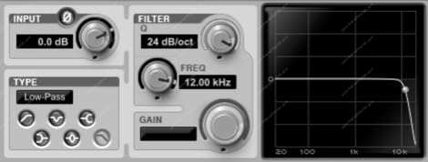
Low pass filter. Here it is set for a cut-off at 12 Khz and a slope of 24 db per octave. For proper anti aliasing use it should have a very steep slope (60 db/oct or more) and a cutoff at the 20 Khz frequency.
This solution will, of course, limit the frequency response of the audio programme within the boundaries of audibility, which has its pros and cons, which I outline below:
PRO - in systems capable of correctly sampling and reproducing frequencies higher than the audible range, which the built-in anti-aliasing filter will limit to 96 and 192 Khz (depending on the system in use), the ultrasonic frequencies can contribute to obtaining subtractive reactions in the audible zone similar to what occurs in acoustics, helping to colour the sound of the audible band in a more natural way, thanks to the contribution of frequencies and beats that would otherwise be lost
AGAINST - in the same high-frequency sampling, the sound engineer will have no acoustic control over any induced high-frequency distortions in the inaudible band, which could produce (by subtraction) undesirable harmonics in the audible zone, creating a considerable degradation of audio quality, which is as insidious as it is intolerable.
A more effective anti-aliasing action is achieved by means of an anti-aliasing filter combined with an oversampling process, offered by converters and plug-ins, which is always advisable when available.
Inter Sample and Over Sample Distortion
Speaking of aliasing, we know that the converters use an interpolation process between two contiguous samples, in order to recreate a simulation of continuous sampling values, similar to the analogue system.
This produces an upward rounding of the intensity values of two adjacent samples.
It will therefore be clear to understand that, by pushing a digital signal to values close to or equal to 0 db, theinterpolation itself will create a distortion.
This risk will be all the greater the lower the sampling frequency of the sampling (and thus its resolution), forcing the system to produce interpolation curves wider in order to compensate for a larger gap between the two contiguous samples.
In addition, certain processes of audio manipulation may create peaks so fast that they exceed the point of digital clipping.
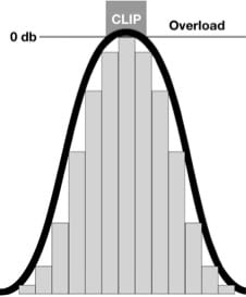
A digitised wave is schematised above, which is defined as the resultant of the level coordinates expressed by the individual samples. The interpolation process intervenes to "round off" the values around these levels, in order to obtain a more harmonic "virtual continuous line". When a digital value touches the 0 db level, clipping will tend to occur due to the overloading of the rounding values created by the interpolation curve.
N.B.
Both risks are particularly delicate when exporting an audio file following a mastering process.
And even when converting and reconverting a master to and from an audio format that uses data compression processes (mp3, aac, etc.), it will be possible to accidentally overshoot the clipping limit.
DC offset
In the audio recording, a DC offset is an undesirable characteristic of a recorded sound.
It occurs in the capture of sound, before it reaches the recorder, and is sometimes caused by obsolete, faulty or low-quality analogue equipment.
L'offset causes the centre 'of equilibrium' of the waveform is not at 0 db, but at a slightly higher or lower value.
This could cause two possible drawbacks:
- clipping of peaks, if the waveform base has been raised - hence the first advice is to monitor the audio programme levels already during recording, to avoid unexpected distortions
- a low-frequency distortion
Once digitised into an audio track, the drawback should be eliminated by means of a special Daw function, if present (DC offset removal).
Typically, this function will also allow us to analyse a 'suspect' file in order to diagnose and eliminate the problem.
If the daw is lacking, the application of a high-pass filter with a drastic cut below the audible band (20 hz or even much less) should in any case eliminate the problem.
In addition to the risk of clipping, the presence of DC offset could also affect the response of a dynamics compressor, so it is always a good idea to remove it as soon as possible.
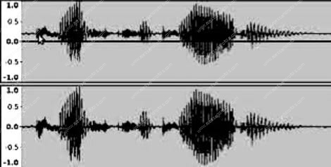
Representation of a waveform with DC Offset (above) and the same normalised (below).
The Montgomery test
Here is a quick summary of a research carried out by theengineer Christopher Montgomery (creator of the OGG and a keen scholar of audio sampling and the acoustic perception), which involved performing numerous tests over the course of an entire year, involving a good number of audiophiles, among whom were several 'insiders'.
The aim of the test was to check whether a good number of experienced listeners were really able to distinguish at thecomparative listening between audio files containing the same sound programme but sampled at different sampling frequencies.
TEST RESULT
None of these experienced listeners could ever reliably distinguish any difference between audio files from sources sampled in very high definition, and those converted from them at different combinations of frequency and number of bits.
As for the bitit should be made clear that the processing of an audio file subjects it to loss of dynamics, so it is advisable to always work with a high number of bits, thus allowing the processes a wide margin of tolerance, in order to avoid any risk of distortion.
The reduction of the definition to 16 bits is now only tolerable at the end of the job, through an appropriate dithering that minimises any handicaps induced by the final conversion.
Concluding Summary
-
-
- it will be sufficient to use the frequencies of 44.1 or 48 Khz both in the audio processing and in producing audio files for the end user
- if the resources of the audio recording and processing system make it possible, it will be advisable to use 88.2 or 96 Khz during production and subsequent manipulation of the audio, whereas higher frequencies would be overpowering
- in particular, mastering processes, not requiring a very high expenditure of daw resources, should be carried out in oversampling, with frequencies double those of the mix
- the use of 24 bits or more will be indispensable during the manipulation of audio and for the export of an archive master, while their use may be considered optional during the export of files destined for the end user, for which operation 16 bits would be absolutely sufficient
- the use of floating point systems is always advisable to make layer management in the daw more practical, faster and safer
-
With regard to the sampling frequencies of the 176.4, 192, 352.8 and 384 Khz systems, in view of the lack of any feedback on the quality that emerged during the tests, Montgomery himself decreed their dubious usefulness.
The sound
By using an appropriate number of bits and adequate sampling frequencies for digital, it is no longer possible to define any superiority between digital and analogue in the area of pure sound, as both offer very different advantages and criticalities, and for this reason hardly commensurable. However, an attempt will be made below to summarise their characteristic differences
- Digital:
- Cleanliness and Clarity: Digital systems tend to produce very clean and clear recordings, with almost no background noise.
- LoyaltyHigh fidelity reproduction of the original sound, with minimal discolouration or alteration.
- DynamicsWide dynamic range, especially with 24-bit or higher formats. The dynamic range of sources is faithfully respected
- Rustle: The noise floor of the system itself is non-existent, although in practice it can be induced in a very small proportion by the input and output converters.
- Analogue:
- Warmth and Character: Analogue recordings are often described as 'warmer' and 'fuller', with a certain sound colouration that can be aesthetically pleasing, although this is actually an alteration, due to elements that have nothing to do with the original sources, but induced by tape fluctuations and the harmonic distortion process of the tape and equipment.
- Natural Saturation: When the tape is overloaded, it produces a harmonic saturation that many find musically pleasing.
- Dynamics: The dynamic range is generally more limited than in digital; at high dynamic values, sources tend to be slightly compressed due to both the relative saturation of the preamplifiers and the 'dynamic restraint effort' of the magnetic tape.
- RustleBackground noise (such as tape hiss) may be more noticeable, but when it is below the audible level it contributes to colouring the sound, which is thus dirtier but also enriched in timbre fullness.
The future of digital
The history of every technology teaches us that traditional processes reach an impassable apex of evolution, while new processes take their first modest steps.
This was the case with analogue which, at the emergence of digital, was indisputably superior to it in almost every respect.
In recent years, we have witnessed a qualitative flanking of the two technologies, albeit with differences that suggest the possibility of an intelligent interaction between the two worlds.
In the future, it will be inevitable that digital will almost totally take the place of analogue, as it will be better and better able to emulate its qualities and character (it is already doing so), while also developing new and exclusive ones, governed by the undoubted and considerable practical advantages inherent in digital management.
A thousand are the 'urban legends' that accompany so many traditional types of equipment that, when endowed with undoubtedly excellent quality, are often considered 'mythological', sometimes surpassing objective reality with myth.
Beyond quality, the special colour of a hardware equaliser is something unique, and so is the progressive reactivity induced by a dynamic valve processor.
This justifies the affection and worship of many sound engineers, who continue to prefer its use.
The quality and success of high-end analogue processors is also confirmed by the effort made by many software designers to emulate the most celebrated hardware devices by designing them in plugin form, with sometimes surprising results.
A personal opinion
Having been able to work in analogue recording at the beginning of my experiences, I understand that many sound engineers like the sound dimension determined by magnetic tape and hardware processors.
Here, however, any honest comparison is often distorted by individual preferences, while what counts is the search for objective quality aimed at the goal to be achieved.
As far as processing is concerned, I have had several opportunities to make direct comparisons between the performance of some of the best analogue processors and the finest digital plug-ins installed in the best DAWs.
I often preferred digital in the area of tonal control and sometimes also in the area of dynamic control, while in other cases the opposite was true.
In general, I could state that:
Precise digital equalisers are generally preferable in the field of surgical equalisation, e.g. during the preliminary stages of equalisation aimed at clearing the sound of unwanted resonances, due to their millimetric precision in locating and controlling the tonal spectrum in a highly selective manner, without introducing any kind of colouration; they are also often preferable in passive tone colouration operations, i.e. when they are used to attenuate a group of frequencies
as a function of active tone colouring, i.e. where an attempt is made to amplify a tonal range, I often achieve more satisfactory results with analogue eqs, but also with their digital emulators (I often use Neve and Pultec), some of which lead to impressive results even in the area of matching the corresponding hardware model.
in the dynamic area, I could perhaps say that precise digital compressors allow detailed and neutral control of the overall dynamics of tracks, while analogue compressors and their digital emulators, although less precise, tend to smooth out dynamic angularities in a more 'adaptable' manner and enrich the harmonic spectrum in a modulated manner, contributing to a rich, gritty and warm sound.
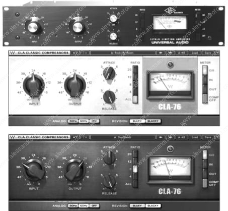
Picture of the famous Universal Audio 1176 hardware compressor (above) and two versions of its emulator in Waves' version, the CLA-76.
Some valuable analogue machines also have their own unique and pleasant 'colour', which some of the most successful emulators in plugin form have partly restored to us.
Consequently, as things stand, the choice will depend on the specific case to be dealt with, personal taste, available budget, and the ability to handle the different issues inherent in both digital and analogue.
As usual, the lack of any bias will be the best guide for the choices and will allow for the construction of a 'mixed' set-up, incorporating some analogue elements in a modern digital context.


Leave a Reply
Want to join the discussion?Feel free to contribute!